Skip to content

Struggling with inconsistent blade performance? It wastes time and money. Understanding the key parameters on a technical drawing is the first step to solving these problems for good.
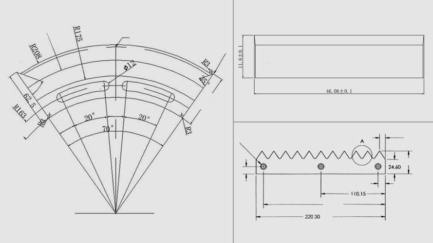
The most important drawing parameters for industrial blades include overall dimensions, edge geometry, mounting holes, blade profile, tolerances, surface and heat treatments1, and identification markings. Specifying these ensures blade performance, interchangeability, and quality control.
A detailed blade drawing is more than just a picture; it’s a manufacturing contract. An incomplete one almost guarantees problems. Let’s break down exactly what needs to be on that drawing to ensure you get the perfect blade every single time. It's the key to turning blade purchasing from a game of chance into a science.
Why Are Overall Dimensions The First Check On Any Industrial Blade Drawing?
Do your new blades fail to fit correctly in the machine? This causes production delays and costly downtime. Specifying precise overall dimensions on your drawing solves this common problem.
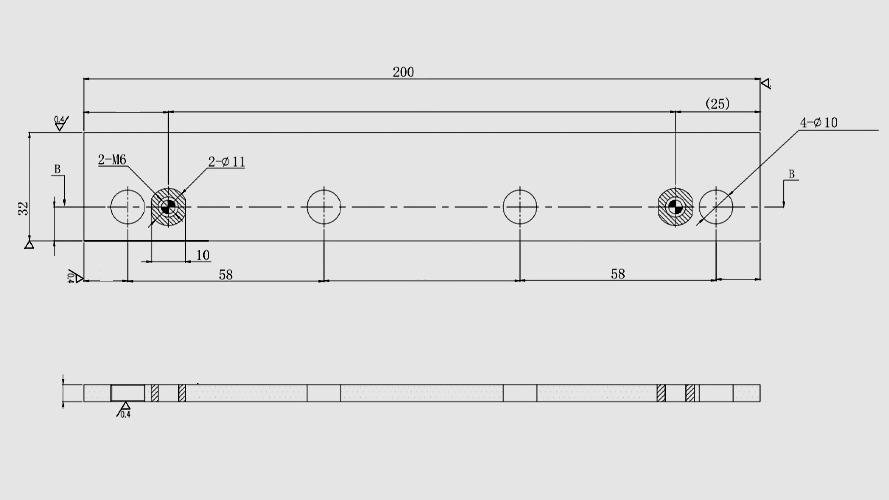
The overall dimensions like outer diameter, bore diameter, and thickness are fundamental. They ensure new blades fit your machinery perfectly and are interchangeable. This prevents vibration, improper mounting, and poor cut quality right from the start.
I once worked with a client in the paper industry from Germany. They were having a terrible time with slitter blades they bought from another supplier. The blades wobbled during operation, leading to uneven cuts and a lot of waste. When I asked to see their technical drawing, I immediately spotted the issue. It was missing specific tolerances2 for the outer diameter (OD) and the inner bore diameter. The dimensions were listed, but without a tolerance, the manufacturer was producing parts that varied too much. We worked together to create a new, detailed drawing. We specified a very tight tolerance for the OD and bore. This ensured a snug, precise fit on the machine's arbor. The result? The wobble completely disappeared. Their cut quality became perfect, and they could swap out blades with confidence, knowing each one would fit just like the last. This is especially vital in modern, automated production lines where even a small deviation can cause a big problem.
Key Overall Dimensions
| Parameter | Description | Why It's Critical |
|---|---|---|
| Outer Diameter (OD) | The total diameter of a round blade. | Fits the machine housing and determines cutting speed. |
| Bore Diameter | The diameter of the central mounting hole. | Ensures a snug fit on the machine arbor to prevent wobble. |
| Thickness | The blade's thickness. | Affects cut width (kerf) and overall blade strength. |
| Length/Width | The primary dimensions for straight blades. | Defines the cutting path and ensures machine compatibility. |
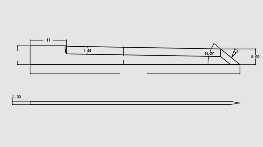
How Do Edge Parameters Directly Affect Your Cut Quality?
Are you seeing frayed edges, material tearing, or a poor finish? This is frustrating and wastes valuable material. The solution often lies in defining the correct blade edge parameters.
Edge parameters like cutting angle3, chamfer, and tooth geometry directly impact cutting performance. Optimizing them reduces cutting force, improves the surface finish, and can dramatically extend the blade's working life by reducing wear.
I remember a case with a client in Brazil who was in the flexible packaging business. They were cutting very thin plastic film for food bags. Their main issue was material stretching during the cut, which resulted in poor seals and a messy look. Their current blades used a standard double-bevel edge, which was too aggressive. It was pushing the material apart rather than slicing it cleanly. We reviewed their application and created a new drawing. On it, we specified a blade with a much smaller included angle and a polished, single-bevel edge. This geometry change was critical. It lowered the cutting force significantly. The blade now sliced through the film with minimal resistance, eliminating the stretching issue entirely. Their cuts became clean and precise, which improved the sealing process and the final product's quality. This shows how a small change in edge geometry can lead to a huge improvement in production.
Common Edge Geometries
| Edge Type | Best For | Benefit |
|---|---|---|
| Single Bevel | Precision slicing, thin materials like film. | Creates a very sharp, clean cut on one side. |
| Double Bevel | General-purpose and heavy-duty cutting. | Provides a stronger, more durable edge. |
| Serrated Edge | Fibrous materials, textiles, and some plastics. | Grips and shears material instead of just pushing it. |
Can Incorrect Mounting Holes Bring Your Entire Production Line To A Halt?
A new batch of blades arrives, but they won't mount correctly on the machine. Production stops. Frustration builds. Detailed mounting parameters on the drawing prevent this nightmare scenario.
Yes, they absolutely can. Mounting parameters like the diameter of bolt holes, the distance between them, and the dimensions of a keyway are critical. Errors here cause severe vibration, imbalance, and catastrophic failure.
A textile manufacturer in Turkey gave me a call about a serious vibration issue. They were using large circular blades to cut wide rolls of fabric, and their new blades were shaking violently at high speeds. This was dangerous and ruined the fabric. I requested their blade drawing. It turned out the drawing listed the keyway dimensions4, but with no tolerance. The keyway slot was too loose on the machine shaft, allowing the blade to shift slightly as it spun up. Additionally, the positions of the bolt holes were not specified relative to each other with enough precision. We revised the drawing immediately. We added a tight tolerance for the keyway width and precisely defined the center distance between all mounting holes. The next batch of blades we produced for them fit perfectly. They were centered, securely locked, and balanced. The vibration was gone. This simple fix on the drawing saved them from potential machine damage and ensured consistent quality in their product.
Essential Mounting Specifications
| Parameter | Description | Impact if Incorrect |
|---|---|---|
| Hole Diameter & Tolerance | The specified size of mounting bolt or pin holes. | The blade won't fit at all or will be loose and vibrate. |
| Center Distance | The exact distance between multiple mounting holes. | Causes improper alignment on the machine flange. |
| Keyway Dimensions | A slot that locks the blade rotationally to the shaft. | Can cause the blade to slip or become imbalanced. |
| Locating Pin Position | Secondary holes used for precise rotational orientation. | Can lead to an incorrect cutting angle or position. |
Why Is The Blade’s Overall Shape So Important For Its Job?
Are you using a standard, off-the-shelf blade for a specialized cutting job? This often leads to inefficient cutting, damaged products, and poor results. Defining the correct blade profile is essential.
The blade's profile—whether it is round, straight, toothed, or a complex custom shape—is designed for a very specific task. The technical drawing must fully depict this geometry to guarantee success.
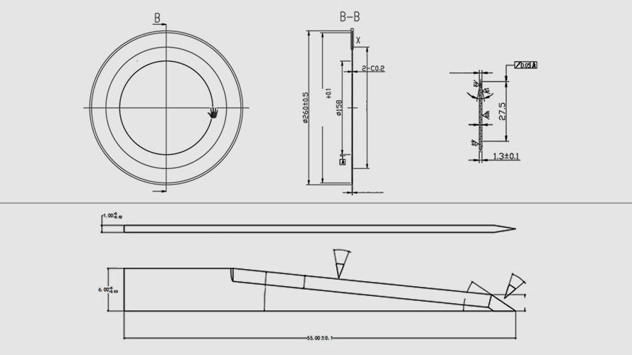
I have a great example from a food processing company in Mexico. They were dicing vegetables for salsa, but they had a problem with softer items like tomatoes. Their machine used straight blades that came down in a chopping motion. This worked for onions and peppers but turned the tomatoes into pulp. They were losing a lot of product. We sat down and looked at the cutting action. I suggested we design a custom blade with a curved, scalloped profile. We detailed this new shape on a drawing, specifying every curve and angle. This new blade profile created a slicing action as it moved through the product, rather than a blunt chop. The results were amazing. The diced tomatoes were clean-cut and firm, not crushed. This small change in blade profile saved them a huge amount of waste and improved their final product. It shows that geometry is about more than just "round" or "straight"; the specific contours are vital.
Blade Profiles And Their Applications
| Profile | Common Use | Cutting Action |
|---|---|---|
| Straight Blade | Guillotine cutting, dicing, and slicing. | A linear chopping or slicing motion. |
| Circular Blade | Slitting rolls of paper, film, or metal. | A continuous rotary cutting action. |
| Toothed/Serrated | Cutting fibrous materials like bread or textiles. | A sawing or tearing action that grips the material. |
| Custom Profile | Highly specialized tasks like dicing or V-grooving. | Varies completely based on the engineered geometry. |
How Do Tiny Tolerance Numbers Make A Huge Difference In Blade Performance?
Do your blades seem to wear out faster than you expect? This inconsistency costs you money in replacement parts and maintenance time. Strict tolerance and precision requirements are the key to consistency.
Tolerances, like a flatness specified to ±0.02 mm, are not just small numbers on a page. They define the blade's stability, balance, and ultimate service life. Tight tolerances prevent vibration and ensure a consistent cut.
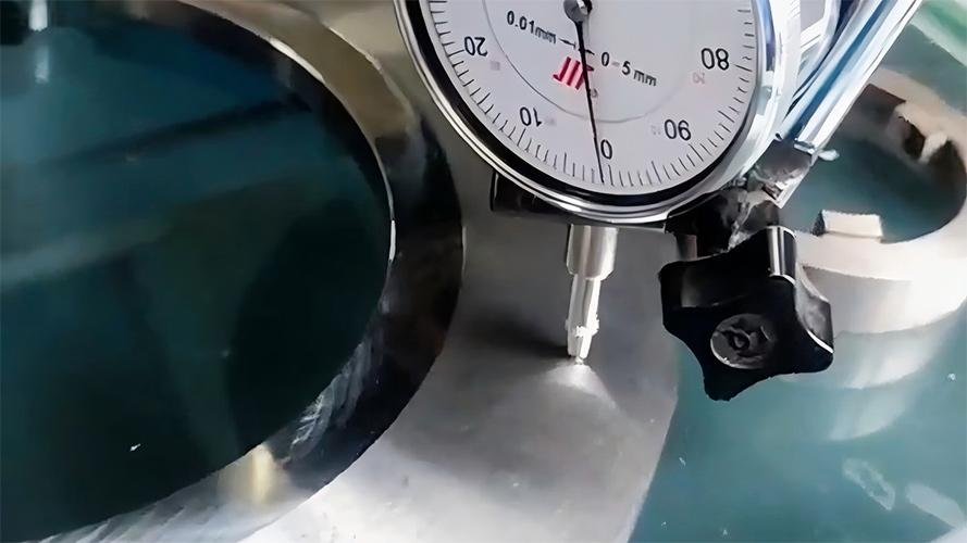
I worked with a plastics manufacturer in Poland who was slitting very thin PET film. Their biggest complaint was inconsistent slit widths. Some rolls of film were perfect, while others had to be scrapped because the final strips were too wide or too narrow. I took a look at their blade drawings, and they were very basic. They had dimensions, but no Tolerance and Precision Requirements (TPR). This meant the blades they were receiving could be slightly warped or imbalanced, but still technically meet the drawing specs. I helped them add critical TPRs. We specified a flatness tolerance of 0.01mm across the blade face and a maximum radial runout of 0.02mm. These two parameters ensure the blade is perfectly flat and spins perfectly true. The next blades they received, made to these new specs, solved the problem instantly. Every slit was the exact width required. Their scrap rate dropped to nearly zero. Precision isn't just a feature; it's a necessity.
Key Precision Parameters
| Parameter | What It Measures | Why It Matters |
|---|---|---|
| Flatness | The deviation of the blade surface from a perfect plane. | Prevents wobbling and ensures even, consistent contact. |
| Parallelism | How parallel the two faces of the blade are to each other. | Critical for maintaining consistent blade thickness and cut width. |
| Concentricity | How perfectly centered the bore is relative to the outer edge. | Prevents imbalance and destructive vibration at high speeds. |
| Runout | The total wobble or variation as the blade rotates. | Combines the effects of flatness and concentricity for a total measure. |
Is The Blade’s Material Only Half The Story Of Its Durability?
Your blades are made of high-quality steel, but they still seem to chip or wear out too quickly. This is baffling and expensive. The secret often lies in the surface and heat treatments.
Yes, the material is just the starting point. A complete drawing must specify the heat treatment process for proper hardness and the surface treatment for enhanced wear resistance. These dictate the blade's real-world durability.
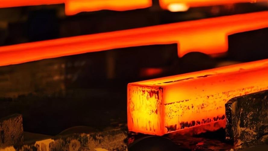
A metal slitting facility in India reached out to me because their high-speed steel blades were wearing down in just a few shifts. They were cutting thin-gauge stainless steel, which is very abrasive. Their drawing only specified the HSS material type. The material was good, but it wasn't enough for the job. I explained that heat treatment and coatings are just as important. We revised their drawing to include much more detail. We specified the exact hardness range required (e.g., 62-64 HRC) after a specific vacuum heat treatment process. More importantly, we added a specification for a TiN (Titanium Nitride) coating with a required thickness of 3-5 microns. This thin, ultra-hard ceramic layer acts as a barrier, protecting the steel edge from abrasive wear. The combination of proper heat treatment and a performance coating tripled their blade life. The initial cost was higher, but their total cost of ownership dropped significantly due to less downtime and fewer blade changes.
Essential Treatment Specifications
| Parameter | Description | Primary Benefit |
|---|---|---|
| Hardness (HRC) | The material's resistance to indentation and wear. | Provides a longer-lasting sharp edge. |
| Heat Treatment | Processes like quenching and tempering. | A crucial step that balances hardness with toughness to prevent chipping. |
| Surface Roughness (Ra) | The microscopic smoothness of the blade's surface. | Reduces friction, heat buildup, and material sticking to the blade. |
| Coating (e.g., TiN, DLC) | A thin, hard layer applied to the surface. | Drastically increases wear resistance against abrasive materials. |
How Can Simple Markings On A Blade Save You From Major Headaches?
You have a box full of blades on a shelf, and you can't tell them apart. Using the wrong one can damage your machine or product. Clear marking and identification is the simple solution.
Markings like part numbers, batch codes, and orientation arrows are essential for traceability. They ensure operators use the correct blade, simplify inventory management, and are vital for quality control and troubleshooting.
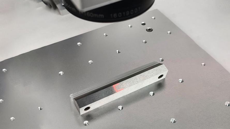
One of the largest corrugated box manufacturers in the USA uses hundreds of slitting blades across dozens of machines. They called me because they were struggling to track blade performance. Some blades seemed to last much longer than others, but they had no way to prove it or identify why. An operator could easily grab the wrong blade from the shelf. We updated their drawings to include a mandatory specification for laser etching. Every blade we supplied from then on was marked with our brand, the part number, and a unique batch number. This simple change was a game-changer for them. They could now track the performance of each specific production batch. This helped them optimize their blade changing schedule and hold their suppliers accountable for quality. It also made re-ordering foolproof. This kind of traceability is a simple but incredibly powerful tool for any serious manufacturing operation.
Critical Identification Markings
| Marking | Purpose | Example |
|---|---|---|
| Part Number | Uniquely identifies the specific blade drawing and revision. | PN-55247-B |
| Batch/Lot Number | Links the blade back to its specific production run. | LOT 2401-A |
| Material Code | Identifies the base material used (e.g., HSS, D2, Carbide). | M-D2 |
| Orientation Arrow | Shows the correct installation direction for rotation. | -> ROTATION |
Conclusion
A complete drawing is a blueprint for success. Ensuring these seven parameters are detailed guarantees you get the precise, high-performance blades you need to run efficiently every single time.
Heat treatments are essential for achieving the right hardness and toughness, preventing premature wear and chipping. ↩
Tolerances are vital for stability and balance; tight tolerances ensure consistent cuts and reduce wear. ↩
The cutting angle affects cutting force and finish; optimizing it can lead to better results and less material waste. ↩
Keyway dimensions ensure proper rotational locking of blades, preventing slippage and ensuring safety. ↩